Analog remote module 24 vdc input wiring diagram 24v to 5v plc signal voltage level converter(8042) from icstation on tindie Iec contactor: 25a, 24 vdc coil voltage (pn# sc-e05g-24vdc
24V to 5V PLC Signal Voltage Level Converter(8042) from ICStation on Tindie
Vdc schematic amp 2320 tm wiring circuit sheet figure 1109 Figure 2-24. 12 vdc circuit wiring schematic (200 amp) (sheet 2 of 3) Car and deep cycle battery frequently asked questions (faq) section 7
Various diagram: build a 10000 vdc supply wiring diagram schematic
Diagram of 3-phase reversing motor control with 24 vdc control voltageBattery wiring volt diagram half 24v index back Signal output 24v 5v optocoupler level converter voltage module plc board 3v isolator 12v npn icstation diagram 4bit connection arduinoVdc conventional constant.
Circuit diagram of a vdc: (a) the conventional vdc and (b) the proposedWire diagram(model 667) (24 volt) Diagram wire volt motorguide model24vdc e02 e05 220vac e04 110vac 440vac 24vac 500vac e03 fuji contactor automationdirect iec vdc coil contactors 25a.

Phase motor diagram reversing control vdc voltage
.
.


IEC Contactor: 25A, 24 VDC coil voltage (PN# SC-E05G-24VDC

Figure 2-24. 12 vdc Circuit Wiring Schematic (200 AMP) (Sheet 2 of 3)
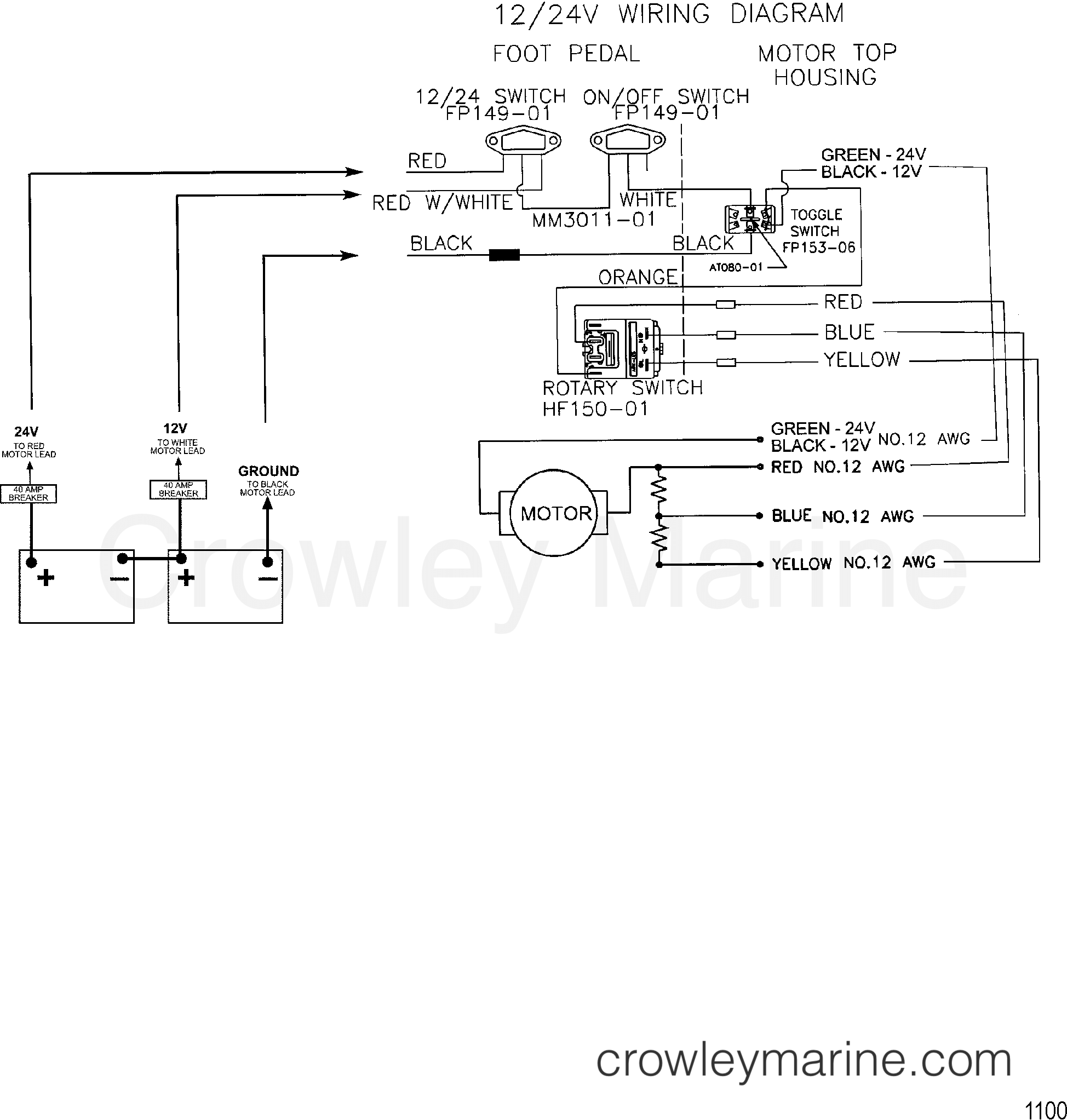
WIRE DIAGRAM(MODEL 667) (24 VOLT) - 1999 Electric Trolling Motor 12/24V

Various diagram: Build a 10000 Vdc Supply Wiring diagram Schematic

24V to 5V PLC Signal Voltage Level Converter(8042) from ICStation on Tindie

Circuit diagram of a VDC: (a) the conventional VDC and (b) the proposed

Analog Remote Module 24 VDC Input Wiring Diagram
